MrRCSound – The Aspire Sound Unit Test

Concepts, Electronica, Scale, Plane Aerial Concepts Belgium, Patric Dietvorst, Aspire, B-17G, Flying Fortress, MrRCSound, Multi engine sound

P-47D Aspire Sound Unit - detail

Tested the MrRCSound Aspire module with one TT25 installed in the foam battery compartment of my B-17G Flying Fortress. First I have tested the Aspire Sount Unit in the B-17G with a single Engine file of a 9 cylinder Wright Cyclone motor

Because the Multi-engine sound files of the 9 cylinder Wright Cyclone motors are not available at this moment, I have used the Multi-Engine sound file for the Consolidated B24 Liberator with 4 14 cylinder radial Pratt & Whitney motors.

And also because the TT25 was very hot I have mounted a cooling element on the element and modified the audio output of the Aspire card at about 75 %. Still, the sound pressure is very high, measuring about 97 db A at 1m. The test was successful. I'm satisfied with the result.

More information about this Aspire sound card and TT25 transducer you will find on the website of MrRCSound and in the RCgroups.

www.mrrcsound.com/aspire-info
RCgroups Aspire sound unit discussion

Photos

Spektrum – Meaningful Telemetry for Airplanes

 Concepts, Electronica, Plane Aerial Concepts Belgium, Patric Dietvorst, AS3X, Spektrum, Telemetry

Meaningful Telemetry - detail

I am using a Spektrum DX9 Black Edition Transmitter in mode 2. The DX9 possesses a number of class-leading features. Easy programming, 250 models. The centerpiece is its incredibly advanced voice and vibration alert system.

I am using the AR9350 9 channel as  RX. This is a new generation of Spektrum™ AS3X® with Artificial 3-aXis stabilization. The AS3X System works behind the scenes to stabilize an airplane in whatever attitude you command. A. small aircraft behaves like a bigger one and can the more wind influence. This multiLink receiver gives you the protection of as main receiver connected to two satellite receivers. By mounting the smaller satellite receivers away from the main receiver in different orientations, the odds of all of them experiencing signal reflection at the same time are reduced to a statistical impossibility.

This RX has built-in Telemetry capability. This telemetry module keeps tabs on the quality of the signal coming to the receiver and send this information back to the transmitter where it is represented on the LCD screen and logged o the SD card.

I am using a Flight Pack Energy Sensor is designed to measure battery capacity used.  By measuring the current the sensor determines how much capacity has been used by your electric power system. This is more accurate than a voltage sensor. Every 60 secs the TX-voice gives the used capacity. When the capacity of the battery is 30% the TX gives a repeating audio alarm you have to clear (push clear button). After this alarm, you have enough capacity to perform a safe landing (if necessary one go-around).

I am using an airspeed sensor (a pitot tube-based pressure measurement which measures airspeed from approximately 20 km/h to 300 km/h. I am using a switch to get the TX-voice telling me the actual speed at the moment I like to know this information. But more important is a vibration alarm when airspeed drops within a safe zone just above stall speed. This is a very good landing aid. Try to stay just above this alarm until you are about 1m above and at the beginning edge of the landing strip. Flare at stall speed when the plane is maximum 50 cm above the field and gentle land the plane and let the plane slow down on the airstrip or the grass field.

Offline, all telemetry data logged on the SD card can be viewed and analyzed on a Windows PC with the Spektrum Telemetry viewer. Some examples are added to the Spektrum photo link on this page.

Landing Gear – Modifications for Grass Fields

 Concepts, Mechanical, Scale, Plane Aerial Concepts Belgium, Patric Dietvorst, AS3X,Eflite, P-47D, Spektrum, Thunderbolt

P-47D Thunderbolt Landing Gear - detail

What makes the best Warbird for grass landing? Something with bigger and particularly sturdy wheels/landing gear. The Eflite P-47D is a tail dragger and with the factory retracts and stock wheels, nose overs are occurring on take off and landings, especially when the grass is not short. A good thing is, the landing gear is wide and there are possibilities to modify the landing gear to improve stability and take flying precautions to successfully take off and land like a scale plane, also on a grass field.

I have exchanged the 2,5″ (5 cm) wheels with Dubro 3″ (7,5 cm) lightweight wheels. It’s possible to retract these wheels. They fit the openings in the wings. Use a copper bus 4-3 mm to adjust the inner diameter of the wheels. Grind away some plastic at one side of the wheel to fit the wide of the wheel on the landing gear.

I change the inclination of the landing gear to use longer bolts and spacers. The wheels are now 2 cm more to the nose of the plane. This makes a real difference.

Take off with Flaps 1/4 out. Give full elevator up before gently apply throttle to get the plane moving. Apply full throttle only when the plane is already rolling through the grass.Take off with a  gentle slope. Retract the landing gear when the plane is airborne. Flaps up when leveling the plane.

Landing with maximum 1/2 flaps deployed, and with a relative fast final approach. (approx. 45-50 km/h). Start losing speed when you are 1m above and at the edge of the grass landing field. Flare when the plane is 50 cm above the field, but keep 10% -15%  throttle so air keeps flowing over the wings and the plane will not tip over. Retract the flaps when you have landed. If you like to taxi, don’t stop the plane first on the grass field. Always taxi with full elevator up and flaps retracted.


Photos

Weathering – To get a real Warbird Look

 Concepts, Plane, Scale, Visualisation Aerial Concepts Belgium, Patric Dietvorst, Eflite, P-47D, Thunderbolt, Vallejo

P-47D Thunderbolt Weathering - detail

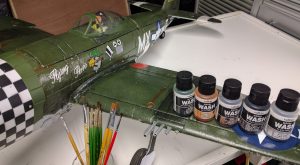
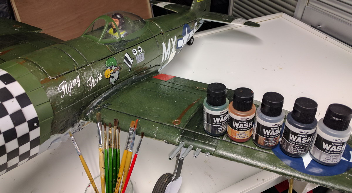
These washes from Vallejo come in medium size 35ml Bottles. There are 12 different colors. For this model I have used 505 (Light Rust), 515 (Light Grey) 517 (Dark Grey), 519 (Olive Green), 521 (Oiled Earth). They are water-based and so thin with water. The wash itself is made with an acrylic resin so that the surface tension of the wash behaves like a solvent-based material, but it has the benefits of clean-up and dilution with simple water. The wash itself dries in around 15-20 minutes depending on the temperature and humidity of where you are working with them. You can also layer washes on top of each other as well. You could suffer some light deterioration of the original coat of paint.

I started with the panel lines. With a small paint, the 517 and brush carefully fill only the panel line. Let 2-3 minutes drying, then use a cloth to wipe away some wash. Wipe carefully in the direction of the panel lines. The idea is, less weathering is better and you can always add some more in a second layer.

The second step is washing the olive green surfaces. With a brush paint the  519 and apply this wash on the surfaces. After 30 to 60 seconds wipe most of the wash gentle with a cloth. Repeat if you like more wash. In the middle part of bigger areas, you best remove more to get a lighter effect. If the wash is to dry to remove use a little water or isopropyl alcohol to remove more. On the lighter surfaces at the bottom of the plane use the 515 wash with the same technique.

The third step is to add some details like dark gun strips (517), rust areas, add some chipping with silver acyl paint. Most details you do not wipe with a cloth. Just apply a little and let it dry.

The fourth step is to paint some elements, like paint the machine guns silver, and dry brush the motor part behind the propeller with some silver strips. You can paint the cowl internally black. I have added I yellow tape inside the front of the cowl and use some varnish to fix the tape.

Fifth step. If you finish the weathering and you are satisfied with the result, you can apply a clear varnish by aerosol. Do not overdo because this only adding weight to your model.

Led Lights – Improve the In Air Visibility

 Concepts, Electronica, Plane, Visualisation Aerial Concepts Belgium, Patric DietvorstAS3X, Fun Cub, Mutiplex, Spektrum

Fun Cub Led Strips - detail

In daylight, you can improve the visibility of an aircraft by using different colors or patterns on top of the wing versus the bottom of the wing. But when sunlight is limited in the morning, in the evening, when it is heavy clouded or there is some fog all colors faint and become gray or black.

Because the battery for the Fun Cub is 3S you can use the balancer connector to get approximately 12 Volts. led strips are available in multiple colors.  I have used short strips with 6 Led green, red, and white to create navigation lights left, right, and in for of the wings. The cables are hidden in the wing with a small cut in the foam and can follow the main spar. Central you can use some simple connectors so you can keep the wings removable. You can cover the electrical wiring with a transparent white tape.

Finally, you have to protect electrical connections and the led strips against humidity. I have used a transparent shrinking tube and used a plastic coating spray from Kontakt Chemie to cover the PCB components.

Fun Cub – Modify the Location of a Flap Servo

 Concepts, Mechanical, Plane Aerial Concepts Belgium, Patric Dietvorst, AS3X, Fun Cub, Multiplex, Spektrum

Fun Cub Flap Servo - detail

Standard the flap servos are mounted identically at the left and right-wing. If you would like to use one flap channel and a split cable you can replace the servo with a reverse servo or and an electronic reverser in the cable, but there is a simpler solution. You can mechanically change the location of the servo, making room by cutting away some foam. The old location you can be filled with some Elapor spare foam.

COG – A good Centre of Gravity

 Concepts, Plane  Aerial Concepts Belgium,  Patric Dietvorst, AS3X, Fun Cub, Multiplex, Spektrum

Fun Cub CoG - detail

Like any other aircraft, the FunCub must be balanced at a particular point in order to achieve stable flying characteristics. The Centre of Gravity (CG) should be at the position 80 mm aft of the root leading edge, i.e. at the fuselage sides. This is correct, but in fig 30 in the manual, the order of the electronic components is not optimal to achieve this CG.

A better order of the electronic is as follows: From propeller/motor; first the ESC motor controller, than the receiver (RX), and most to the back the battery (3S 2200 mAh). With my battery and this plane, the battery had to be put completely to the back above the air ventilation opening on the bottom of the plane. I have put two horizontal carbon rods so the battery can not move vertically. A piece of Velcro keeps the battery horizontally fixed during flight.

I have glued two small pieces of sanding paper (20mm x 10mm) at the bottom of the plane at centers of gravity about 30cm apart. This makes it easy to put your finger at the Centre of Gravity with sufficient grip to balance the ready to fly this airplane (battery mounted)..

Oracover – Ironing Film on Foam

 Concepts, Plane, Visualisation Aerial Concepts Belgium, Patric Dietvorst, AS3X, Fun Cub, Multiplex, Spektrum

Fun Cub Look - detail

Changed the look of this plane with Oracover ironing film on top of the foam. Cut more than a hundred separate squares 30×30 mm of Oracover film. This film gets sticky without shrinking at a temperature of 70-100 °C. Do not overdo it because the foam can expand a little under the film if you heat too long.

Landing Gear – Modifications for hard Landings

 Concepts, Mechanical, Plane Aerial Concepts Belgium, Patric Dietvorst, AS3X, Fun Cub, Multiplex, Spektrum

Fun Cub Landing Gear - detail

Bent two same hooks in 2 mm copper wire for the wheel-side and two other hooks in 2 mm copper wire for the fuselage-side. Grind (with Dremel or sandpaper) the locations where the hooks should be connected to the 3mm tempered landing gear rod intensively. This is important to make good soldering between hook and landing-gear. If you like you can strengthen the connection by winding some thin copper wiring before soldering.

Use 2×2 elastic bands the reinforce the landing gear. Remove the bands if you are nog using the airplane, so the elastic bands last longer.