Concepts, Mechanical, Scale, Plane Aerial Concepts Belgium, Patric Dietvorst, AS3X,Eflite, P-47D, Spektrum, Thunderbolt
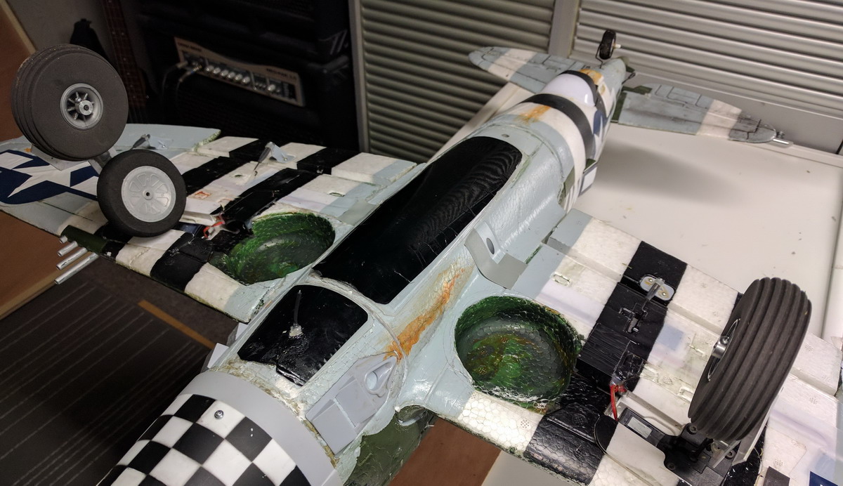
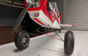
What makes the best Warbird for grass landing? Something with bigger and particularly sturdy wheels/landing gear. The Eflite P-47D is a tail dragger and with the factory retracts and stock wheels, nose overs are occurring on take off and landings, especially when the grass is not short. A good thing is, the landing gear is wide and there are possibilities to modify the landing gear to improve stability and take flying precautions to successfully take off and land like a scale plane, also on a grass field.
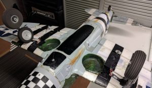
I have exchanged the 2,5″ (5 cm) wheels with Dubro 3″ (7,5 cm) lightweight wheels. It’s possible to retract these wheels. They fit the openings in the wings. Use a copper bus 4-3 mm to adjust the inner diameter of the wheels. Grind away some plastic at one side of the wheel to fit the wide of the wheel on the landing gear.
I change the inclination of the landing gear to use longer bolts and spacers. The wheels are now 2 cm more to the nose of the plane. This makes a real difference.
Take off with Flaps 1/4 out. Give full elevator up before gently apply throttle to get the plane moving. Apply full throttle only when the plane is already rolling through the grass.Take off with a gentle slope. Retract the landing gear when the plane is airborne. Flaps up when leveling the plane.
Landing with maximum 1/2 flaps deployed, and with a relative fast final approach. (approx. 45-50 km/h). Start losing speed when you are 1m above and at the edge of the grass landing field. Flare when the plane is 50 cm above the field, but keep 10% -15% throttle so air keeps flowing over the wings and the plane will not tip over. Retract the flaps when you have landed. If you like to taxi, don’t stop the plane first on the grass field. Always taxi with full elevator up and flaps retracted.
Photos
Concepts, Mechanical, Plane Aerial Concepts Belgium, Patric Dietvorst, AS3X, Fun Cub, Multiplex, Spektrum
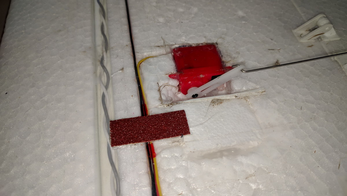
Standard the flap servos are mounted identically at the left and right-wing. If you would like to use one flap channel and a split cable you can replace the servo with a reverse servo or and an electronic reverser in the cable, but there is a simpler solution. You can mechanically change the location of the servo, making room by cutting away some foam. The old location you can be filled with some Elapor spare foam.
Concepts, Plane Aerial Concepts Belgium, Patric Dietvorst, AS3X, Fun Cub, Multiplex, Spektrum

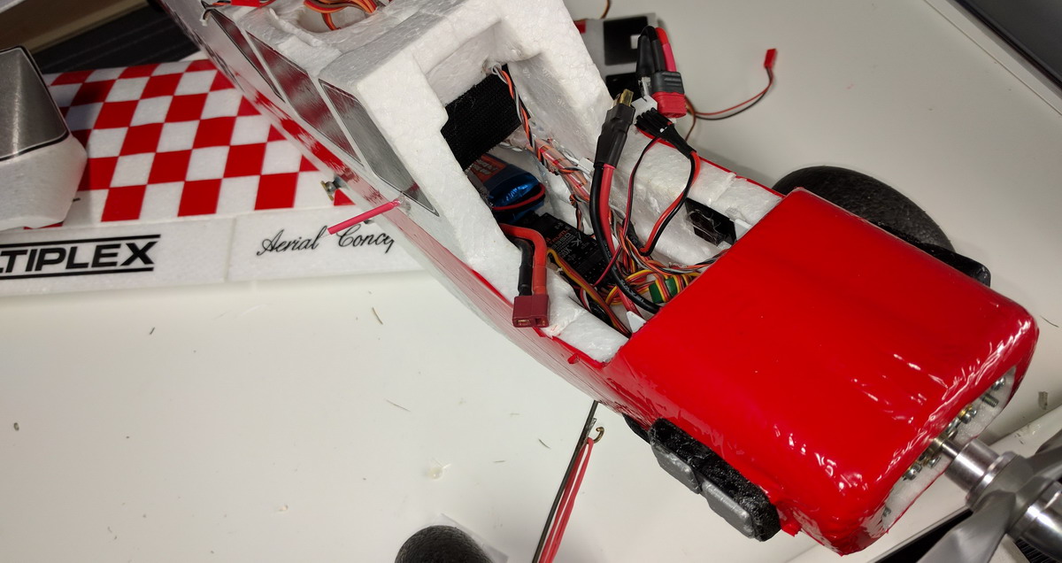
Like any other aircraft, the FunCub must be balanced at a particular point in order to achieve stable flying characteristics. The Centre of Gravity (CG) should be at the position 80 mm aft of the root leading edge, i.e. at the fuselage sides. This is correct, but in fig 30 in the manual, the order of the electronic components is not optimal to achieve this CG.
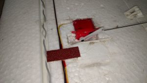
A better order of the electronic is as follows: From propeller/motor; first the ESC motor controller, than the receiver (RX), and most to the back the battery (3S 2200 mAh). With my battery and this plane, the battery had to be put completely to the back above the air ventilation opening on the bottom of the plane. I have put two horizontal carbon rods so the battery can not move vertically. A piece of Velcro keeps the battery horizontally fixed during flight.
I have glued two small pieces of sanding paper (20mm x 10mm) at the bottom of the plane at centers of gravity about 30cm apart. This makes it easy to put your finger at the Centre of Gravity with sufficient grip to balance the ready to fly this airplane (battery mounted)..
Concepts, Mechanical, Plane Aerial Concepts Belgium, Patric Dietvorst, AS3X, Fun Cub, Multiplex, Spektrum
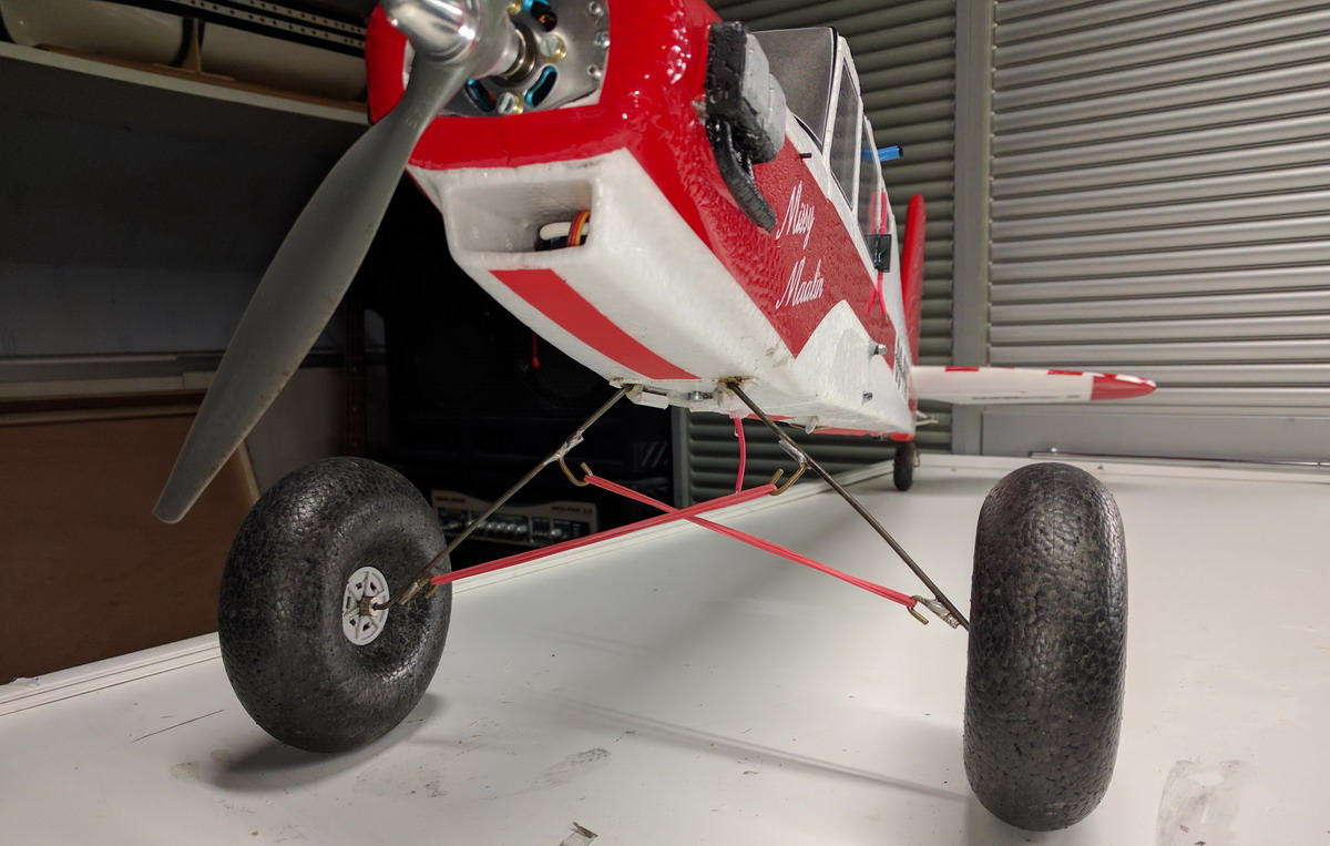
Bent two same hooks in 2 mm copper wire for the wheel-side and two other hooks in 2 mm copper wire for the fuselage-side. Grind (with Dremel or sandpaper) the locations where the hooks should be connected to the 3mm tempered landing gear rod intensively. This is important to make good soldering between hook and landing-gear. If you like you can strengthen the connection by winding some thin copper wiring before soldering.
Use 2×2 elastic bands the reinforce the landing gear. Remove the bands if you are nog using the airplane, so the elastic bands last longer.